Understanding the Basics: Why Testing a Relay Matters
When an electronic device suddenly stops working, one of the most overlooked culprits is often the relay. This small but critical component acts as an electrically operated switch that controls circuits, helping devices turn on, off, or change states automatically. Knowing how to test a relay not only saves time and money but also deepens your understanding of how your electrical systems function.
At ODG, we understand that precision and reliability are the backbone of every electrical system. Whether you’re troubleshooting automotive electronics, industrial machinery, or home appliances, mastering relay testing can help you diagnose issues effectively before considering costly replacements.
What You Need Before You Begin
Testing a relay doesn’t require advanced equipment — just the right tools and a careful approach. Before diving in, gather the following essentials:
- Digital Multimeter – for checking resistance, voltage, and continuity.
- Jumper Wires – to safely apply power to the relay coil.
- Power Source (usually 12V DC) – for energizing the relay during tests.
- Relay Datasheet or Diagram – to identify pin layout and specifications.
Having these tools on hand makes the process smoother, safer, and far more accurate.
Step 1: Inspect the Relay for Visible Damage
Begin with a visual inspection. Examine the relay housing carefully for signs of burning, corrosion, or melting — indicators that it may have overheated or failed. A damaged relay casing or discolored pins often signals internal issues that render it unsafe or unreliable.
If you notice a burnt smell or physical deformation, it’s best not to continue testing. In such cases, immediate replacement is the safest route.
Step 2: Identify the Pin Layout
Every relay has several pins, each serving a distinct purpose — coil pins, common (COM), normally open (NO), and normally closed (NC) contacts. To proceed accurately, consult the relay’s datasheet or the schematic printed on its casing.
- Coil Pins: Receive the voltage that energizes the relay.
- COM (Common): The central contact that connects to either NO or NC.
- NO (Normally Open): The circuit is open until the relay is energized.
- NC (Normally Closed): The circuit remains closed until the relay is energized.
Understanding this layout ensures that your test readings make sense and prevents accidental short circuits.
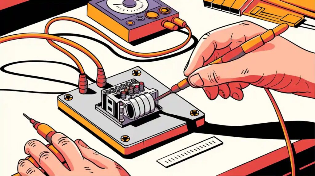
Step 3: Test the Coil with a Multimeter
Switch your multimeter to resistance (ohms) mode and place the probes on the coil terminals. A healthy relay coil should show a specific resistance value (typically between 50 and 1,000 ohms, depending on the relay type).
- Normal Reading: Indicates an intact coil.
- Infinite Resistance (OL): The coil is broken or open.
- Zero Resistance (0 ohms): The coil is shorted.
This simple test tells you whether the relay can still respond to an electrical signal or if it has failed internally.
Step 4: Energize the Relay
Next, apply the rated voltage (e.g., 12V DC) across the coil terminals using jumper wires. You should hear a distinct click — this sound confirms that the internal switch is moving.
If you don’t hear anything, double-check your power connections and verify that the coil voltage matches the relay’s rating. A silent relay may indicate a broken coil or mechanical failure.
Step 5: Check Contact Operation
While the relay is not energized, use your multimeter’s continuity mode to measure between the COM and NC pins. You should hear a beep (continuity present), indicating a closed connection.
Then, apply power again to the coil. Now, check between COM and NO pins — you should hear the continuity beep. This confirms the relay’s switching mechanism works correctly.
If you don’t detect continuity when expected, it’s a clear sign that the internal contacts are stuck, burnt, or misaligned.
Step 6: Reconfirm by Measuring Voltage Output
For added precision, measure the output voltage at the relay’s output pins while the coil is energized. The reading should match the input voltage (or close to it) depending on the circuit design. Inconsistent readings may signal worn contacts or high internal resistance.
This step helps validate whether the relay can still handle current effectively, especially important in high-load systems such as automotive relays or industrial machinery.
Step 7: Interpret the Results
After performing all these checks, you can confidently determine whether your relay is functional or needs replacing:
- All Tests Pass: The relay is working correctly.
- Coil Fails Resistance Test: Replace the relay — it won’t energize properly.
- Contacts Don’t Switch: The internal mechanism is likely stuck or burnt.
- Voltage Drop Detected: Contacts may be oxidized, affecting performance.
By systematically verifying each step, you avoid unnecessary replacements and ensure your devices operate safely and efficiently.
Common Mistakes to Avoid
Even experienced technicians can make small errors that lead to incorrect readings. Keep these points in mind:
- Never exceed the rated coil voltage — it can burn the coil instantly.
- Don’t test on a live system without isolating the relay.
- Avoid touching probe tips while testing to prevent false readings.
- Use insulated tools to minimize the risk of short circuits.
Attention to these details not only protects your components but also ensures your safety during the process.
How ODG Supports Reliable Testing and Quality Assurance
At ODG, we go beyond just supplying components — we ensure every part meets the highest standards before it reaches your hands. Our strict QA system and professional QC team inspect every product to guarantee reliability, durability, and safety.
As proud members of ERAI and holders of certifications like ESD, AS9120B, ISO9001, and ISO14001, we maintain unwavering confidence in the quality of the components we supply. This commitment allows engineers, technicians, and OEM partners worldwide to trust ODG for every testing, maintenance, and replacement need.
Our experienced staff bring deep technical expertise to help customers not only find the right components but also understand how to test and apply them effectively. This collaborative approach ensures every project achieves both performance and longevity.
A Final Thought on Relay Testing
Mastering how to test a relay empowers you to solve problems faster, maintain efficiency, and keep systems running without interruption. The process doesn’t just identify a faulty part — it enhances your understanding of how electrical systems communicate and respond to control signals.
At ODG, we believe precision begins with knowledge. Every technician, hobbyist, and engineer who learns to test a relay effectively gains more than diagnostic skill — they gain control over their craft. As technology evolves and circuits grow more complex, one small relay test can make the difference between downtime and dependable performance.
Follow ODG:
YouTube: https://www.youtube.com/@Origin_Data Facebook: https://www.facebook.com/OriginDataGlobalLimited Twitter: https://twitter.com/Origin_IC Tiktok:
https://www.tiktok.com/@origin_data Szxlxc:
https://www.szxlxc.com